Choosing a Geared Motor in 2026 requires more than matching torque and speed from a catalogue. Electric motor systems consume about 50% of global electricity, according to the International Energy Agency. Small efficiency losses can therefore become significant operating costs. The International Federation of Robotics reported 541,302 industrial robots installed worldwide in 2023. That growth increases demand for compact, precise, and reliable drive systems in conveyors, packaging machines, warehouse equipment, and robotic joints.
The correct selection begins with the real load. Measure starting torque, continuous torque, output speed, duty cycle, shock loading, and allowable backlash. A conveyor carrying heavy cartons may need a helical or planetary gearbox, while a quiet medical device may benefit from a compact spur or low-noise design. Check the motor’s rated voltage, thermal limits, brake requirements, mounting position, and IP protection rating. Environmental details matter. Dust, washdown water, cold rooms, and frequent reversing can quickly expose a weak specification.
Industry reports can guide the market direction, but they cannot replace application testing. A manufacturer’s efficiency figure may reflect ideal conditions, not your machine at 40°C. That distinction matters. Engineers should compare gearbox service factors, bearing life, lubrication intervals, and actual acceleration profiles before purchasing. A spreadsheet can still mislead. The best Geared Motor is not always the smallest, cheapest, or most powerful option; it is the unit that delivers stable motion, acceptable noise, manageable heat, and dependable service throughout its expected life. Testing one representative assembly remains a practical safeguard for 2026 decisions.
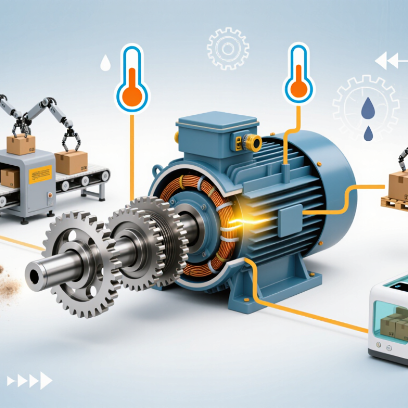
A geared motor combines an electric motor with a gearbox to produce controlled rotary motion. The motor creates speed and torque, while the gears reduce speed and increase usable force. Inside the housing, several gears transfer power through meshing teeth. This process helps a small motor move a heavier load with better control.
In practical equipment, the output shaft may turn slowly enough to operate a conveyor, lifting mechanism, or compact actuator. Gear ratio determines the trade-off. A higher ratio usually delivers more torque but reduces output speed. Efficiency also matters, because friction creates heat and wastes energy. A motor can look powerful on paper, yet perform poorly under continuous load. That detail is easy to miss.
Tips: Measure the required load, speed, duty cycle, and mounting space. Check starting torque, not only running torque. Keep the gearbox aligned with the driven equipment. Listen for unusual clicking or vibration during testing. These signs often appear before serious damage. I would also leave a small safety margin, although an oversized motor may cost more and operate inefficiently. Selection is rarely perfect on the first attempt. Review the real operating data after installation, then adjust the specification when necessary.
How to Choose a Geared Motor in 2026?
Torque, speed, power, and duty define the real selection problem. Start with the driven load, not the motor catalogue. Measure required torque at the output shaft, then include starting torque, friction, incline forces, and shock loads. A conveyor moving 80 kilograms may need modest running torque but much higher starting torque. Calculate output speed from line speed and roller diameter. Then estimate power with P = T × ω, while allowing for gearbox efficiency and service margin.
The International Energy Agency reports that electric motor systems consume more than half of global electricity. This makes correct sizing an energy issue, not only a mechanical one. Select a duty rating using the actual operating cycle. IEC 60034-1 distinguishes continuous, short-time, and intermittent duties. Record starts per hour, operating minutes, reversals, ambient temperature, and peak load duration. A 25% margin may be sensible, but an automatic 50% margin can waste energy and reduce control quality. My practical mistake has been trusting average torque too much. Peak events often decide the gearbox size. Check the manufacturer’s thermal data and allowable radial loads against the shaft arrangement.
Tips: Create a simple load profile with time, torque, and speed. Validate it with a torque sensor if possible. Recheck the calculation during cold starts and jam conditions. The U.S. Department of Energy’s Motor Systems Market Assessment also stresses system-level efficiency, so inspect couplings, alignment, and controls—not just motor efficiency. Don't let a clean spreadsheet hide uncertain field measurements.
| Requirement | What to Define | Engineering Formula or Method | Practical Reference Values | Example Design Input |
|---|---|---|---|---|
| Load Type | Identify whether the load is constant, variable, shock-loaded, or affected by acceleration and friction. | Consider starting torque, peak torque, inertia, friction, incline angle, and external forces. | Conveyors often have high starting torque; mixers may have variable torque; fans generally have lower starting resistance. | Horizontal conveyor carrying a steady product load with moderate starting resistance. |
| Required Output Torque | Determine the continuous torque and the maximum short-duration torque required at the gearbox output shaft. |
For a drum or pulley: T = F × r T = torque in N·m, F = tangential force in N, r = radius in m. |
Small automation mechanisms may require less than 10 N·m; conveyors and lifting systems can require tens to thousands of N·m. | Tangential force: 800 N; drum radius: 0.10 m; continuous torque: 80 N·m. |
| Service Factor | Allow for load variation, shock, frequent starts, ambient conditions, and operating hours. | Required gearbox rating = calculated continuous torque × service factor. | Typical preliminary values: 1.0–1.25 for smooth loads; 1.25–1.75 for moderate variation; 1.75 or higher for severe shock or frequent cycling. | 80 N·m × 1.5 = 120 N·m minimum rated output torque. |
| Output Speed | Define the required operating speed, acceptable speed tolerance, and any acceleration or deceleration limits. | For a rotating drum: v = π × D × n / 60 n = rpm, D = drum diameter in m, v = surface speed in m/s. |
Geared motor output speeds commonly range from approximately 5 to 500 rpm, depending on the application and gearbox ratio. | Drum diameter: 0.20 m; required belt speed: 0.63 m/s; output speed: approximately 60 rpm. |
| Gear Ratio | Match the motor speed to the required gearbox output speed while considering efficiency and available ratios. | Gear ratio ≈ motor speed ÷ required output speed. | A 4-pole motor commonly operates near 1,500 rpm at 50 Hz or near 1,800 rpm at 60 Hz, with actual speed affected by slip. | 1,500 rpm ÷ 60 rpm = approximately 25:1. |
| Motor Power | Select enough motor power to deliver the required torque at the target speed without continuous thermal overload. | Mechanical output power: P(kW) = T(N·m) × n(rpm) / 9550. | Common small geared motor ratings include approximately 0.12, 0.18, 0.25, 0.37, 0.55, 0.75, and 1.1 kW. | 80 N·m × 60 rpm ÷ 9550 = 0.50 kW mechanical output; select a motor rating that covers gearbox losses and service conditions. |
| Gearbox Efficiency | Account for power losses in the gear mesh, bearings, seals, and lubrication system. | Motor input power ≈ required mechanical output power ÷ total gearbox efficiency. | Approximate efficiency varies by design, ratio, and operating conditions; multi-stage gearboxes may be less efficient than single-stage units. | At an assumed total efficiency of 85%, 0.50 kW ÷ 0.85 = approximately 0.59 kW input power. |
| Duty Cycle | Specify operating hours, starts per hour, run time per cycle, idle time, and load profile. | Duty cycle (%) = operating time ÷ total cycle time × 100. | S1 indicates continuous duty; intermittent operation may be designated S2, S3, S4, or another duty classification depending on the cycle. | Runs 45 minutes and stops 15 minutes each hour: 75% duty cycle; verify thermal suitability for the selected motor. |
| Starting and Peak Torque | Define the torque needed during startup, acceleration, jams, product loading, and reversing. | Peak torque must remain within the motor, gearbox, shaft, key, coupling, and brake limits. | A starting torque requirement of 150%–250% of running torque is possible in high-inertia or heavily loaded systems. | Continuous torque: 80 N·m; estimated starting torque: 160 N·m; confirm the gearbox peak torque rating is higher than this value. |
| Operating Environment | Define ambient temperature, humidity, dust, water exposure, corrosive agents, altitude, and installation location. | Select suitable enclosure protection, insulation class, lubrication, seals, and corrosion resistance. | Indoor industrial environments often use IP55 or higher; washdown, outdoor, or dusty environments may require a higher protection level. | Indoor environment with dust and occasional moisture; specify an enclosure and sealing level suitable for the installation conditions. |
| Electrical Requirements | Confirm voltage, frequency, phase, starting method, control system, and variable-frequency drive compatibility. | Verify rated current, overload capacity, speed range, braking requirements, and compliance with the installation electrical system. | Typical industrial supplies include single-phase or three-phase AC systems at 50 or 60 Hz; exact voltage depends on the installation location. | Three-phase AC supply, 400 V, 50 Hz, with variable-speed control through a suitable drive. |
| Final Selection Check | Compare the calculated requirements with the motor and gearbox ratings before approval. | Check continuous torque, peak torque, output speed, power, thermal capacity, duty cycle, mounting, shaft load, and service factor. | The selected unit should not operate continuously at its maximum rating unless the manufacturer’s thermal and mechanical limits explicitly permit it. | Target: at least 120 N·m rated output torque, approximately 60 rpm output speed, approximately 0.59 kW input power, and suitable continuous-duty thermal capacity. |
Note: The reference values are typical engineering ranges for preliminary selection. Final sizing should use the actual load profile, gearbox efficiency, thermal limits, peak torque data, mounting arrangement, and applicable electrical and safety requirements.
How to Choose a Geared Motor in 2026?
The best gearbox depends on load behavior, speed, space, and maintenance access. Helical gearboxes suit conveyors, mixers, and packaging lines requiring high efficiency and steady torque. Bevel-helical units fit right-angle layouts without sacrificing much efficiency. Worm gearboxes remain compact and economical, but their sliding contact creates more heat and energy loss. Planetary gearboxes handle high torque in a small footprint. They suit robotics, mobile equipment, and demanding positioning systems. Cycloidal designs tolerate shock loads well, although their cost and weight may challenge smaller machines.
Efficiency deserves closer attention. The IEA’s Energy Efficiency 2023 report states that motor systems consume roughly half of global electricity. A gearbox choice can therefore affect years of operating cost. Check rated torque, peak torque, duty cycle, backlash, thermal limits, and lubrication requirements. Do not size only from motor horsepower. That shortcut often fails during startup.
Tips: Record actual load cycles for one week. Include jam conditions and frequent reversals. Ask for efficiency data at your real speed, not only the catalog’s best point. In dusty or wet areas, verify sealing and inspection access. A spreadsheet helps, but it can miss vibration, installation errors, or poor alignment. That is an uncomfortable limitation. When uncertain, compare two gearbox types through a measured pilot test.
How to Choose a Geared Motor in 2026?
Choosing a geared motor starts with the machine, not the catalog. Measure the required output speed, torque, and running time under real conditions. A conveyor moving heavy boxes may need high starting torque, even when its average load looks modest. Calculate torque from load, drum radius, friction, and acceleration. Then add a practical safety margin, usually based on measured peaks rather than guesses.
Match the motor speed to the gearbox ratio. An incorrect ratio can create overheating, poor positioning, or unnecessary energy use. Check the duty cycle carefully. Intermittent operation, frequent starts, and reversing loads stress the motor differently from steady running. Voltage, frequency, altitude, and ambient temperature also affect performance. In a hot enclosure, cooling may be weaker than the specification suggests.
Protective requirements matter in the installation area. Dust, moisture, washdown, and vibration may require suitable enclosure protection and stronger mechanical support. Confirm shaft loads, mounting position, brake needs, and allowable backlash before ordering. A neat spreadsheet can still mislead. I have seen designs fail because engineers used rated torque instead of starting torque. Leave room for uncertainty, but avoid oversized motors that run inefficiently at light loads. Test a representative load when possible, and record temperature, current, noise, and stopping behavior. Small field measurements often expose assumptions that drawings hide.
The chart compares the continuous output torque required by four typical applications with the design torque used for geared motor selection. Design torque includes an application-specific service factor to account for starting loads, shock, duty cycle, and load variation. Select a geared motor whose rated continuous torque meets or exceeds the continuous requirement and whose allowable peak torque exceeds the design torque.
The reference operating points are calculated from the mechanical power relationship P = T × 2π × n / 60, where P is power in watts, T is torque in newton-metres, and n is speed in revolutions per minute.
Start with the load, not the catalog. Record starting torque, duty cycle, ambient temperature, speed, and allowable noise. An undersized gearbox overheats quickly. An oversized unit wastes money and may operate inefficiently.
Safety begins with worst-case conditions. Check stall torque, thermal limits, shaft strength, braking behavior, and enclosure rating. Match the IP rating to washdown, dust, and humidity. Use physical guarding and a verified emergency-stop circuit. IEC 60034-30-1 defines motor efficiency classes, while ISO 13849-1 helps evaluate safety-related control functions. These standards do not replace a site risk assessment.
Efficiency deserves closer attention. The IEA estimates that electric motor systems use roughly half of global electricity, making small losses financially important (IEA, Energy Efficiency 2024).
Compare total system efficiency, not only the motor’s nameplate value. Include gearbox losses, inverter settings, partial-load operation, and standby consumption.
The U.S. Department of Energy recommends matching motor and drive capacity to actual operating conditions (Improving Motor and Drive System Performance, 2022). A high-efficiency motor can still waste energy when the gearbox is poorly selected.
Maintenance should be visible before purchase. Choose accessible oil ports, replaceable seals, standard bearings, and clear inspection points. Ask for lubrication intervals and expected backlash growth. Vibration and temperature sensors can reveal misalignment early.
Yet sensors are not magic. Dirty probes and ignored alerts create false confidence. In practical installations, a simple monthly inspection may outperform an advanced system nobody checks.
I would also confirm spare-part availability, repair procedures, and technician training before approving the final motor.
A geared motor combines an electric motor with a gearbox. The motor supplies rotation, speed, and torque. The gears reduce speed and increase usable force. It can move a heavier load with better control.
A higher ratio usually increases output torque. However, output speed becomes lower. A slow shaft may operate a conveyor or lifting mechanism. The trade-off is easy to underestimate.
Helical gearboxes suit conveyors, mixers, and packaging equipment. Bevel-helical units support right-angle layouts. Worm gearboxes are compact but can produce more heat. Planetary designs provide high torque in limited space. Cycloidal designs handle shock loads well.
Check output speed, starting torque, running torque, and duty cycle. Also review peak torque, backlash, thermal limits, and lubrication needs. Confirm voltage, frequency, mounting space, and shaft loads. Do not rely only on motor horsepower.
Starting torque helps overcome the initial resistance of a load. A conveyor carrying heavy boxes may need strong starting force. Average running load can look harmless. Startup may tell a different story.
Frequent starts, reversals, and intermittent use increase mechanical stress. High temperatures can weaken cooling inside an enclosure. Dust, moisture, washdown, and vibration may require better protection. Check sealing and inspection access carefully.
Friction creates heat and wastes energy inside the gearbox. Worm gearboxes may lose more energy through sliding contact. A highly rated motor can still perform poorly under continuous load. Catalog efficiency may not match your real speed.
Measure temperature, current, noise, vibration, and stopping behavior. Listen for clicking during operation. Check alignment with the driven equipment. Record actual load cycles, including jams and reversals. Small tests reveal hidden assumptions.
Choosing the right Geared Motor in 2026 begins with understanding how it combines an electric motor with a gearbox to reduce speed while increasing usable torque. Start by defining the machine’s required torque, operating speed, power demand, load profile, starting conditions, and duty cycle. These details help determine whether the system needs intermittent, continuous, reversing, or variable-speed operation. Selecting the appropriate gearbox type also depends on space, transmission efficiency, noise, backlash, shock loads, and the required output arrangement.
The motor and gearbox must be matched to real operating conditions, including voltage, ambient temperature, humidity, installation position, duty frequency, and expected load variations. Before making a final decision, review energy efficiency, thermal performance, overload capacity, enclosure protection, braking needs, and control compatibility. Safety should include guarding, reliable mounting, electrical protection, and emergency stopping provisions. Regular lubrication, inspection, alignment checks, and temperature monitoring can extend service life and reduce unexpected downtime. A complete evaluation of performance, environment, maintenance, and lifecycle cost will support a dependable selection.

YWOO Motor